


Dc Power Systems Application
* Small scale program controlled exchanges
* Access network
* Transmission equipment
* Mobile communication
* Satellite communication ground station
* Microwave communication
Dc Power Systems Feature
EVS’s Dc Power Systems are designed for wireless broadband access, fixed-line applications, Internet backbone and datacenters.
Our reliable, energy-efficient telecom power solutions protect against grid power interruptions and fluctuations and help operators reduce OPEX
and their carbon footprint.
This Rectifier Systems is for commucication,
Output voltage -54V,Output current 0-60A;Its features include input over/under-voltage protection, output over-current protection, output
over-voltage protection.
EVS Telecom Rectifier System ,dc power supply , with the following features and functions:
Dc Power Systems Information
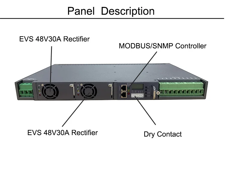
1.Dc Power Systems 48v dc rectifier Power Supply with Modbus Snmp
2. 48V Rectifier Hot swap and Plug and Play;
3 .N+1 redundancy,each module available in 30A@48Vdc;
4 .AC /DC distribution system for AC input/ DC output distribution and protection;
5. RS485, Modbus,SNMP communication for remote control;
6.Compact design and embedded modular system, support power system and module sleep, efficient mixing, energy saving;
7.High Efficiency with low EMI. CE Safety and EMC certification
8. the Dc Power Systems has high power factor greater than 0.98;
9. there are input under voltage, input voltage, output voltage, output current limiting, output short circuit, over temperature protection;
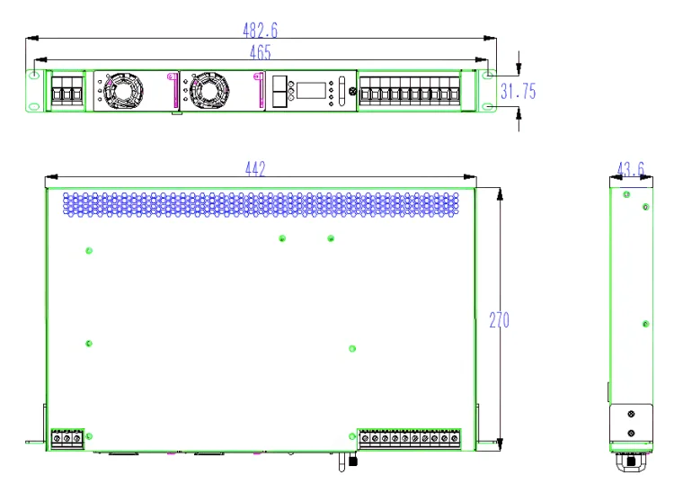
10.Small size, height 1U, 2*48V30A evspower 48V rectifier


Dc Power Systems Electrical Characteristics:
1 | Evspower Dc Power Systems Input Characteristics | ||||||||||
No. | Items | Technical Specifications | Unit | Remarks | |||||||
1.1 | Input rated voltage | 200—240 | Vac | ||||||||
1.2 | Input voltage range | 90—290 | Vac | OR 100-400VDC | |||||||
1.3 | Input Current | ≤20 | A | Lowest input voltage, rated load | |||||||
1.4 | inputvoltage frequency | 50/60 | Hz | ||||||||
1.5 | Power factor | ≥0.99 | rated input voltage, rated load | ||||||||
1.6 | Input Shock Current | ≤30 | A | 264Vac | |||||||
2 | Output Characteristics | ||||||||||
No. | Items | Technical Requirements | Unit | Remarks | |||||||
2.1 | Output Rated Voltage | 54 | Vdc | ||||||||
2.2 | Output current range | 0—60 | A | Inutpu voltage:176—290Vac. | |||||||
0—30 | A | Inutpu voltage:90—175Vac | |||||||||
2.3 | Output voltage range | 53.5 | Vdc | ||||||||
2.4 | Efficiency | ≥96% | 220Vac input,output 54Vdc/60A. | ||||||||
≥92% | 110Vacinput ,output54Vdc/30A. | ||||||||||
2.5 | Output ripple & noise | ≤200 | mVp-p | Rated load, frequency band is limited to 20MHz | |||||||
2.6 | Turn-on output delay | 3—8 | S | Vin=220Vac | |||||||
2.6 | Output rising time | ≤200 | mS | Output voltage rises from 10% to 90%, rated load. | |||||||
2.7 | Turn on/off overshoot | ≤±5 | %Vo | ||||||||
2.8 | Combined regulation | ≤±1% | |||||||||
2.10 | Transient Response | Overshoot | ≤ ±5 | %Vo | 5%—50%—25% or 50%—75%—50% load change. | ||||||
Recovery time | ≤ 200 | µS | |||||||||
2.11 | Phone weighed noise voltage | ≤2 | mV | ||||||||
2.12 | p-pk value noise | ≤400mV | 0—300KHz | ||||||||
2.13 | Wide frequency noise voltage | ≤100 | mV | 3.4—150KHz | |||||||
≤30 | 0.15—30000KHz | ||||||||||
2.14 | Disperse noise | ≤5 | mV | 3.4—150KHz | |||||||
≤3 | 150—200KHz | ||||||||||
≤2 | 200—500KHz | ||||||||||
≤1 | 500—30000KHz | ||||||||||
3 | Battery Management Characteristics | ||||||||||
No. | Items | Technical Requirements | Unit | Remarks | |||||||
3.1 | Floating charge current limiting | 10±1.5 | A | ||||||||
3.2 | Battery undervoltage protection point | 42.5—43.5 | V | Cut load,protect battery | |||||||
4 | Other Characteristics | ||||||||||
No. | Items | Technical Requirements | Unit | Remarks | |||||||
4.1 | MTBF | 100,000 | H | ||||||||